How to Install Hotbodies Race Bodywork on the Yamaha R3
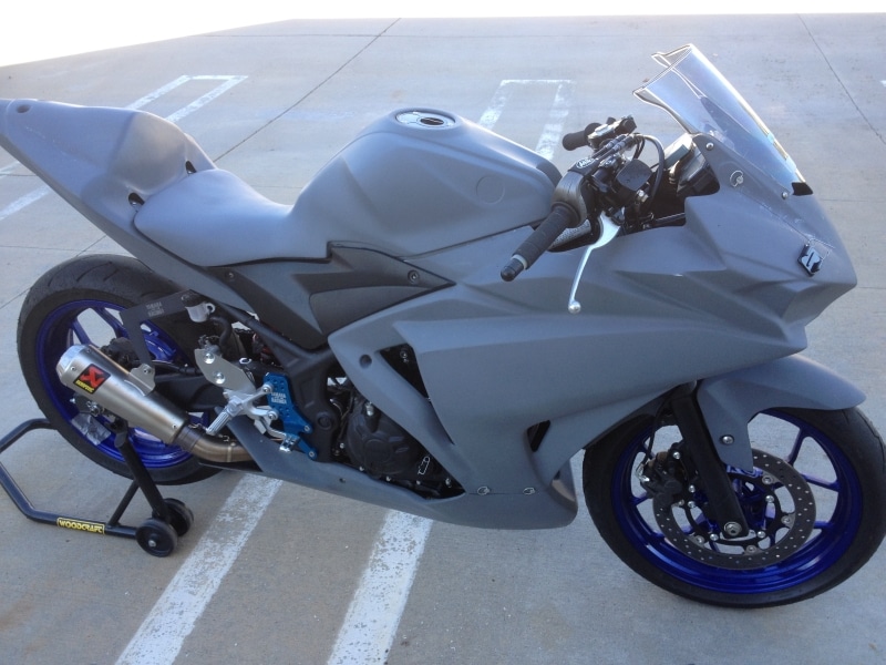
This post will cover in extreme detail how to install the Hotbodies fiberglass race bodywork on the Yamaha R3 using the NortonFab Motorsports Quick-Release Mounting Kit:

If you follow these instructions closely, you’ll end up with a set of race bodywork that not only fits excellent, but is easy to remove and install over and over again. Trust me, take the extra time now, and you’ll be SOOOO glad you did later.
To make this install go smoothly, you will need a few tools:
Drill bits, I recommend using a #1 (1/8″-1/2″) step drill bit and a #3 (1/4″-3/4″) step drill bit to drill the fiberglass such as these:
The cheapo ones will work just fine for a couple uses, but they take awhile to ship from China. I like the Unibit ones, I’ve had good luck with them lasting and they are available immediately with prime shipping. Plus, I like that the 1/4″ tip on the larger one is longer, which makes it easy to punch 1/4″ holes in fiberglass bodywork without oversizing the hole.
You will also need a 1/8″ regular drill bit for the rivet holes. It’s possible to use the 1/8″ tip of the #1 step drill to drill the rivet holes, but it’s very easy to accidentally drill too far and oversize the holes. You only get 1 chance and you’ll be sad if you oversize them… Here’s the drills I used:

You will also need a Dremel or similar rotary tool with a small 80 grit sanding drum attachment. I’ve been using a Black and Decker RTX for years because it has a larger motor than the Dremel brand tools. I also have a flex shaft extension and keyless chuck on mine.

You will need a rivet installation tool such as this:
You can also pick one of these up as part of a kit from any auto parts store for about $15.
Lastly, I strongly recommend picking up one of these combination rasp/files. This is definitely one of the most used tools I own, and comes in handy for removing and shaping fiberglass quickly:
I recommend installing the bodywork in this order:
Remove kickstand and bypass kickstand switch
Upper w/ windscreen
Lower
Tail Section
Tank Cover/SBK Seat
Front Fender
You will reuse a lot of the OEM hardware, grommets, and inserts from the OEM plastic fairings, so keep everything handy until you are finished.
First, follow the instructions here to remove the kickstand and bypass the kickstand switch:
How to remove the kickstand from the Yamaha R3
Next up is the upper fairing, however, the trick to getting a good fit between the upper and the lower is to drill them together off the bike.

Use a sharpie and mark the upper like the photo below. Measure from the back edge of the upper (the edge closer to the tail of the bike) and make a mark at 1 1/4″ and 5″ inches, 1/2″ up from the edge. This is where your DZUS fasteners will be.


Drill both marks to 1/4″ using your step drill bit.

Next, align the upper and lower section and hold them together. Use your sharpie to mark the lower through the 1/4″ holes you just drilled (I used a clamp so I could take a picture, but you can just hold them together with your free hand).


Now drill the lower with your step drill bit to 1/2″ diameter.

Take one of your DZUS receptacles and hold it up on the front of the lower, centered over the 1/2″ hole, and mark the rivet locations on each side for both fasteners. Double check your marks to be sure they line up with the receptacles holes and make sure they are centered around the 1/2″ hole. It’s okay to remark these if its not perfect. It’s important to get these marks as perfect as you can so the rivets and receptacles line up (you can see in the second photo that I remarked the one on the right to get it centered better).


Drill the rivet holes with a 1/8″ drill bit.

Rivet the receptacles in place as shown with the supplied 1/8″ aluminum rivets.


Use your DZUS fasteners to clip the upper and lower together and make sure everything fits properly. You may have to adjust the receptacles so that the clamping pressure is good. You can squeeze the receptacles closed with pliers, or pry them open slightly with a flat blade screw driver.


Once you have a good fit, remove the clips and separate the upper and lower so you can drill the side mounting hole on the upper. Drill the side hole to 1/4″ in the center of the recessed hole.


Repeat these steps on the other side.
The next step is to mount the quick release DZUS fasteners at the top of the upper. Remove the rubber boots on the mirror mounts on the upper fairing stay, and use the supplied M6 flat head screws to mount your two quick release DZUS fastener brackets to the mirror mount on each side. It does not matter which bracket goes on which side. You may have to use pliers to close the receptacle slightly so the bracket will sit flush with the fairing stay.


Now, place the upper fairing on the bike by spreading it as you slide it on from the front. The left side, middle mount has an M6 stud sticking out. Place your drilled hole over this and attach the upper fairing loosely with the original OEM nut used in this location. I had to remove the washer because it would have wedged into the hole. Attach the right side middle mount loosely using the OEM M6 bolt from this locations, also shown in the picture below. Do not tighten these down yet, they are just to keep the upper lined up properly while you drill the top holes.


Use your sharpie to make a mark on each side in the middle of the mirror mount 1 1/2″ from the upper point as shown in the photos below. Drill these marks to 1/4″ diameter with your step drill. They should be in line with the DZUS receptacle behind the fairing (or at least close enough that you can flex the bodywork a little to get them lined up). Fiberglass warps pretty easily, but if you drill these in the indicated place, when you flex the bodywork to line them up with the receptacle, your bodywork should be nice and straight on the bike.


Mount the upper with these two DZUS fasteners to hold it in place so you can mount the windscreen. Then drill the four marked mounting windscreen holes in the upper fairing to .25″ with your step drill bit.

The windscreen must be trimmed away around the mirror mounts so it can be mounted directly to the upper fairing without interference. This takes a little care with a dremel or bench grinder, but saves a ton of hassle in the future, because the screen will just stay mounted to the upper whenever you remove the upper and you never have to fuss with it. Remove the marked material in the picture below on each side so the windscreen fits around the mirror mounts. Test fit it as you go and only remove as much material as you have to so it fits.


Leave the four rubber well nuts installed in the windscreen and attach the windscreen to the bodywork with the four OEM M5 screws.


Now it’s time to finish mounting the lower. Drill the two side holes out to 1/4″ with your step drill bit.


Start on the right side of the bike, and loosely bolt up the lower with the OEM bolt shown below, then move to the left side of the bike and loosely install the left side OEM bolt.


Attach the lower to the upper with the four DZUS fasteners (two on each side).

The lower may interfere with the frame near where the kickstand was, and with the chain in the back. Mark both areas with a sharpie, and use a dremel or air saw to trim both areas as shown below.


All done with the lower, now let’s move on to the tail section.
***Important*** The tail section is a VERY tight fit to get on and off the bike. I have installed and removed my tail section, along with tail sections from a couple other sets of bodywork, so I know it’s possible to do without breaking the bodywork, but it definitely creaks and cracks each time. I was even able to successfully install and remove the Hotbodies color form tail, which has a gelcoat outer layer and is stiffer than the standard primer bodywork. Here’s a short video showing how to do it:
With that being said, the most recent time that I removed my tail section, it split when I pulled it over the rear seat brackets. Major bummer seeing how it’s already painted and wrapped with graphics…

That was the last straw for me, so I decided to go ahead and cut off the rear seat brackets to make it easier to get the tail on and off. I will leave this decision up to you, as it isn’t necessary, but if your bike is for race use only, I would consider cutting off the rear seat mounting brackets to make the tail easier to get on and off without damaging it. Once they are cut off, use some black spray paint to touch up the subframe so it doesn’t rust.


Drill the two rear mounting holes on the top of the tail section to 1/4″ with your step drill.

Drill the one mounting hole circled below on each side where the tail section mounts to the frame. Do not drill any other holes in the tail section at this time.


Slide the tail section over the tail and mount it with the four M6 bolts with washers shown below. You may have to temporarily move the fuse box inside the subframe until you get the tail section half way on. Watch the video above for help getting the tail section on.


Once you have the tail section installed, you can choose to drill any of the remaining marked holes and install the OEM black plastic clips. I decided not to install any of them. In my experience, the clips are too weak and will only break in the future when trying to install or remove the bodywork. They don’t add any strength and it’s just extra work and extra holes in the bodywork, so I leave them out.
Next up is the tank cover/sbk seat. This piece requires the most attention with the dremel, but if you follow these instructions closely, it’s simple to do, and everything will fit great.
The fuel cap opening in the tank cover is a little too small for the rubber trim of the fuel cap to fit. Set the tank cover in place so you can see how much material needs to be removed, then use a rounded file or rasp or a dremel to remove a little material so the tank cover will clear the fuel cap. I found that two even passes around the inside lip with my rasp removed enough material for a nice fit.


Next, drill out the front mounting hole of the tank cover to 1/2″ with your step drill bit. I recommend pilot drilling it in the center from the top, and opening it up to 1/2″ from the back.


Use the mounting hardware from the OEM tank cover for the front hole including the rubber grommet, steel insert, and M6 bolt. First insert the rubber grommet, then slip the steel insert in from the bottom.


Install the tank cover and mount the front with the indicated bolt so you can line up the two seat bolts.

Press the seat down and note how the mounting tabs line up with the mounting holes below. Use your sharpie to mark the tabs in the center of the mounting holes while pressing the seat down all the way.


Drill the mounting tabs on your sharpie marks and open up the holes slightly larger than 1/4″ so the special shoulder bolts included in the kit fit through the hole past the shoulder and sit flat against the tabs.


Screw the tank cover in place by the front bolt and the rear two shoulder bolts. The shoulder will bottom out on the mounting tab on the rear mounts and protect the fiberglass tabs from getting crushed and damaged over time.


Now’s it’s time to mark and drill the gas tank mounts on the side of the tank cover. The mount on the right side lines up great, but the mount on the left side has been a little off on the two tank covers that I’ve personally mounted. Use your sharpie to mark the center of the mounting tabs behind the tank cover mounts before you drill.
Left Side:

Right Side:

Drill the tank cover on your marks. DO NOT DRILL THE TANK COVER WHILE IT’S ON THE BIKE!!!! The gas tank is directly behind the tank cover, and you have to drill these holes out to 1/2″. I repeat, DO NOT DRILL THE TANK COVER WHILE IT’S ON THE BIKE!!!! Remove the tank cover and drill these two holes out to 1/2″, you will be using the same rubber grommet and steel inserts that you used on the front mounting hole.


Because you will be using the rubber grommets and steel insert which has a flange, you have to dremel out around the drilled hole that is off a little so the grommet will sit flat. You also have to dremel a little bit of material off of the back of both sides so that the mounting tab isn’t too thick to install the rubber grommet.

Left Side:


Right Side:


Install the grommets on both sides and press the steel inserts in from the inside of the tank cover.


Install the tank cover back on the bike with all of the hardware. Use these black bolts with 8mm hex heads (use an 8mm to install them, not the Phillips head, the Phillips gets stripped easily. The bolts should line up now with the tabs behind on the gas tank.


With the upper, lower, tank cover, and tail sections mounted, we can now install the grommets and rivet nuts for the black plastic side panels.

Recover these rubber grommets and screws from the OEM bodywork, and locate the 4 gold M5 rivet nuts from your hardware kit.

There is a small plastic tab near the front on the back of each black plastic side panel. If you want, you can try to cut these slots into the bodywork, but I’ve found that they are totally unnecessary and I recommend just breaking them off. It makes the install easier. I went through the trouble to cut the slots into my bodywork the first time, and then broke one of the tabs off on accident removing the panels. The panels have a screw right next to where the tab is anyway, so the tab doesn’t do anything. I just used pliers to break off the other one.


First, you want to drill the grommet mount on the tank cover. It has the least amount of extra material so you can’t adjust the position at all anyway. You can drill it with a step drill, and open it up with the step drill, or drill it then open it up with a dremel or a file. However you do it, you have to make it an oval the same shape as the indent like the picture below. The air box is behind the panel, so if you drill it in place, be careful not to put a hole in your air box. I removed mine to drill it.


The fiberglass around this hole is also too thick to install the grommet. Use your dremel to remove some material from the front and back face to make the tab thinner so the grommet will sit flat when you install it.
Right Side:


Left Side:


Reinstall the tank cover back on the bike, and hold the black plastic side panels up to the side of the bike. Press the plastic pin into the grommet on the tank cover, and line up where the bottom pin sits to mark where to drill the hole for the lower grommet. Mine was slightly off from the mark in the fiberglass. Mark and drill the other grommet hole. Dremel out the fiberglass as necessary and install the other rubber grommets the same way you did the ones on the tank cover.


Now clip the black plastic side panel into the 2 grommets and mark where to drill the front and back screws. You can wiggle the panel a little to line everything up before you mark it.


Drill your marked holes out just larger than 1/4″ so the gold rivet nuts fit through.


To install the rivet nut, hold the back side of the rivet nut with pliers or vise grips and screw in an extra M5 bolt. The two unused black M5 bolts from the gas tank work well. Do not install the black plastic piece while you are installing the rivet nuts. Hold the rivet nut still while you tighten the bolt to crush the rivet nut and crimp it onto the fiberglass panel. Clamp it down tight, then remove the bolt. It’s tight enough if it doesn’t spin when you remove the bolt or attach the plastic panel later.


Before you install the rear rivet nut, you have to make a decision. The OEM bolt will not be long enough unless you grind the tab thinner with your dremel before you install the rivet nut. If you don’t want to do this, you can simply install the rivet nut and use a longer bolt, like the extra black M5 bolts from the OEM gas tank cover. Or, you can grind the tabs thinner before you install the rivet nuts and then the OEM bolts will work. I’ll show both ways.
Here I show leaving the tabs thick, this will require longer bolts when finished to attach the black plastic side panels:


Here I show grinding the tabs down with a dremel so the OEM bolts will work and match the other two bolts:


Almost done! Last up is the front fender. See how it’s dark out now for the photos of the fender? lol
Here’s the hardware from the OEM fender that you will be using:

Drill out all four pre-marked holes in the fender to 1/2″. Then use your larger step drill bit to drill out the rear holes a tiny bit larger because the rear grommets with the chrome steel inserts are slightly larger.


Install the rubber grommets and steel inserts in the front holes like you did with the tank cover, steel inserts go in from the inside.


For the rear holes, install the rubber grommets first, then slide the steel pieces over the grommet with the nut, then insert the steel insert.


Now mount the fender to the forks with the OEM bolts, and you’re done!!!!!!!!!!!!!!!!!!!!! WOOOOOOOOOOOOOOO!!!!!!!!!!!!!


You must be logged in to post a comment.